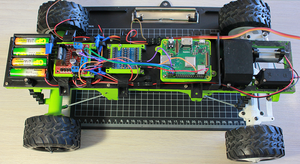
List of equipment required for the project:
- Raspberry Pi 3 model A+
- Logic level converter from 3.3V to 5V
- L298N brushless motor driver
- Battery 5V 2700 mAh
- MG995 servo
- Brushless motor
In this article, we will consider the process of 3D printing and assembling a truck model, analyze the technical aspects and features of connecting devices for controlling electric motors, and also talk about the difficulties encountered during the project implementation.
This project is a continuation of a series of articles about remote control of self-propelled platforms using a Raspberry Pi microcomputer. In the previous article, we installed a Raspberry Pi on a Chinese 1:10 scale pickup model and replaced the radio control module with Wi-Fi control.
In this article, we decided to go further and change the design of our car model. A ready-made truck model project for 3D printing was taken as a basis. The chosen project has a number of advantages. The model provides an independent suspension system, drive is distributed to all 4 wheels, and it is possible to additionally install a differential lock. The size of the truck model allows placing all necessary equipment.
3D printing and assembly of the truck model
While wandering through the vast expanses on thingiverse.com, I came across an interesting 3D truck model project by user MrCrankyface. The project immediately interested me with its complexity, many parts for 3D printing, and many additional metal parts that had to be purchased separately. But first things first.
Link to the project on the Thingiverse: 3D printed RC truck
Printing
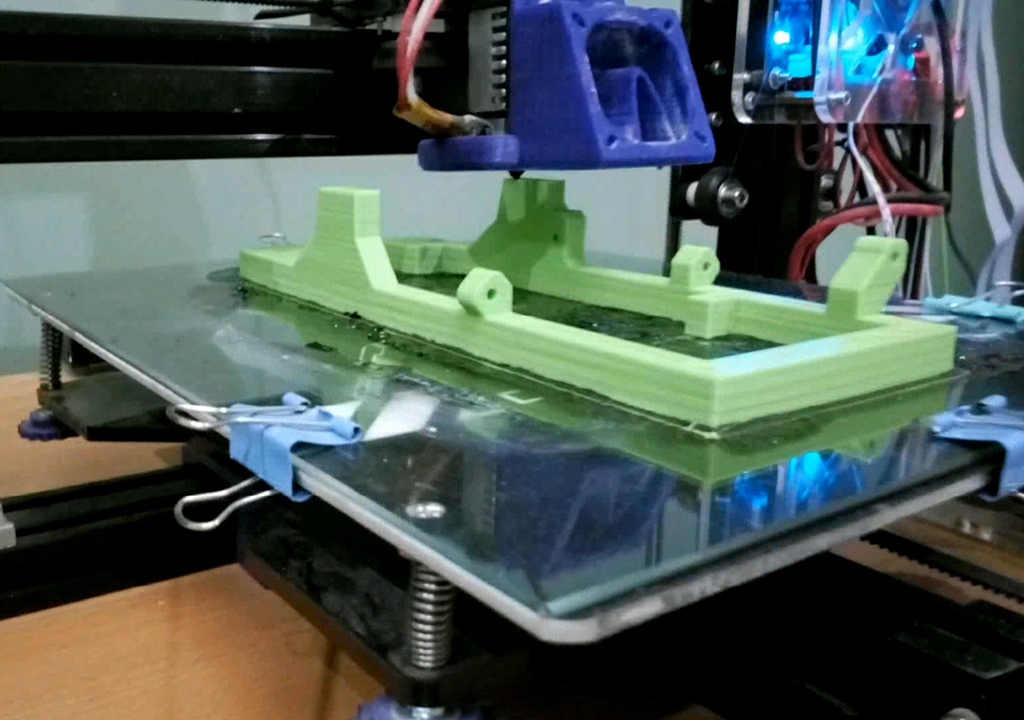
During 3D printing, we encountered a standard set of problems: poor adhesion (when parts came unstuck and warped), delamination of printed parts, and a banal mismatch in the dimensions of mating parts (solved by adjusting the 3D model).
We solved the adhesion problem by using the technology of lubricating the printing surface with ABS glue. ABS glue is easy to make by simply dissolving a small amount of ABS plastic with dichloroethane in a glass, well-sealing container. Then, before each print, the glue is applied to the print surface in a thin layer using an ordinary brush (better before heating the bed).
We solved the problem of part delamination simply by increasing the temperature of the printing nozzle, as well as the bed temperature. For our ABS plastic, the suitable printing parameters were 245 degrees nozzle temperature and 100 degrees bed temperature.
Assembly
For assembling the model, it was necessary to buy additional metal fasteners to connect the printed 3D parts. The full list of required components can be found on the author’s project page (see note). Some parts were available in local stores (such as M3 and M4 bolts, studs, and nuts), some had to be ordered online (such as ball joints for suspension mounting and bearings for rotating parts).
The model itself consists of a load-bearing central frame measuring 7 cm * 40 cm, to which the suspension and power section are attached, a central differential, axles, a brushed electric motor, and a servo drive acting as a steering motor.
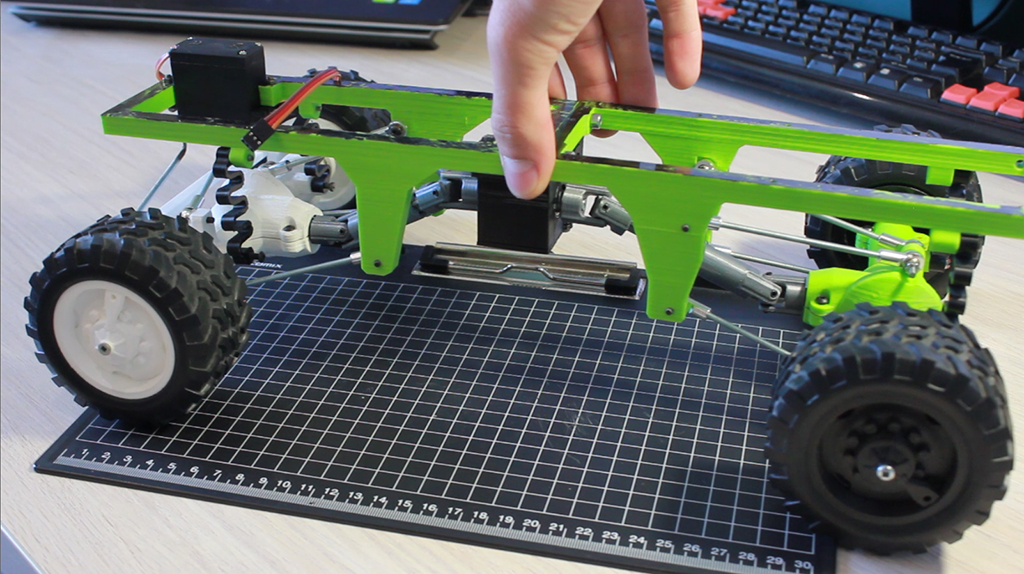
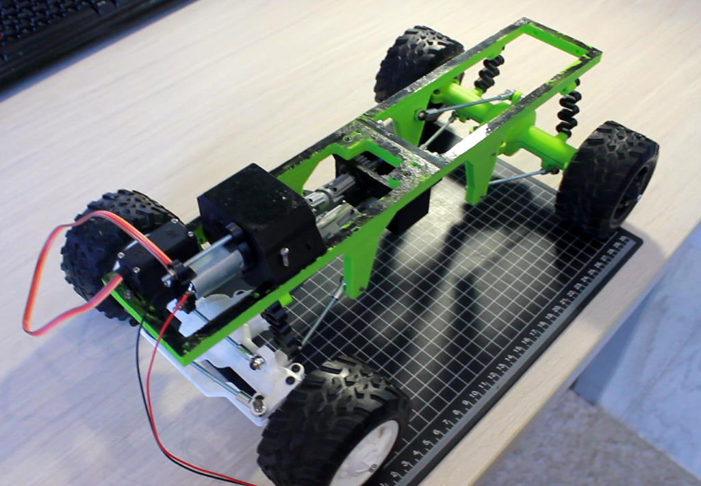
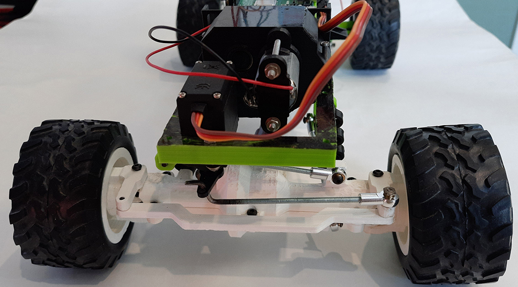
The image above shows the steering mechanism of the front wheels. An M3 stud was bent and used as a steering rack going from the servo to the steering mechanism on the front axle.
The shock absorbers were printed on a 3D printer. This model also provides for the installation of factory air shock absorbers for radio models.
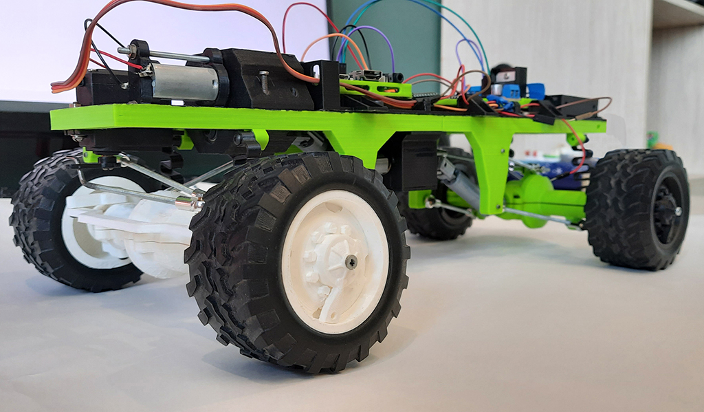
The tires for the wheels were taken from a Chinese radio-controlled model from the previous project. The rims were designed in a 3D editor specifically for the size of these tires and the mounts to the truck model axles. The design of the wheels of the legendary Russian Ural truck was taken as the basis for the wheel rim design.
Development and 3D printing of a platform for equipment
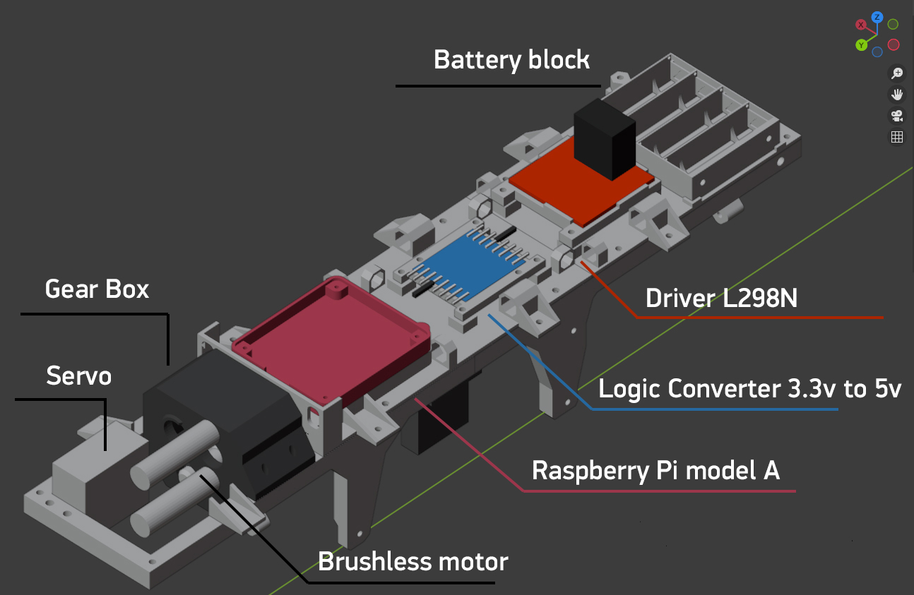
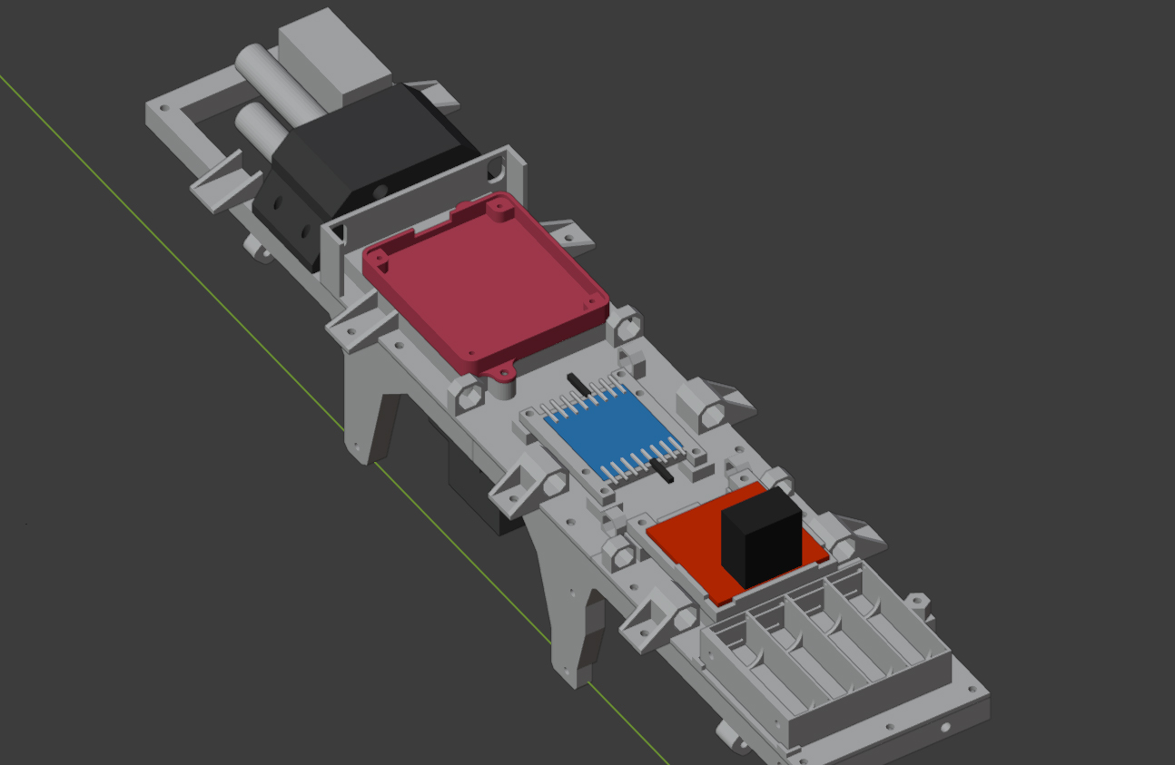
To reliably place the equipment on the model body, an additional 3D model of a platform with mounts for installing circuit boards with the Raspberry Pi microcomputer and motor drivers was developed. All dimensions were taken from the specifications for each individual electronic component. Special slots were provided on the platform for routing wires. In the rear part of the body there is a battery block. On the sides, the platform has mounts for installing the body, which will be printed in the following articles.
For convenience of 3D printing, the platform model was divided into two parts. 3D printing of all platform parts took about 7 hours. Printing was done with 100% infill and supports. After printing, the 3D-printed electronics platform was installed and secured to the truck frame. All electronic components were placed in their respective mounting areas.
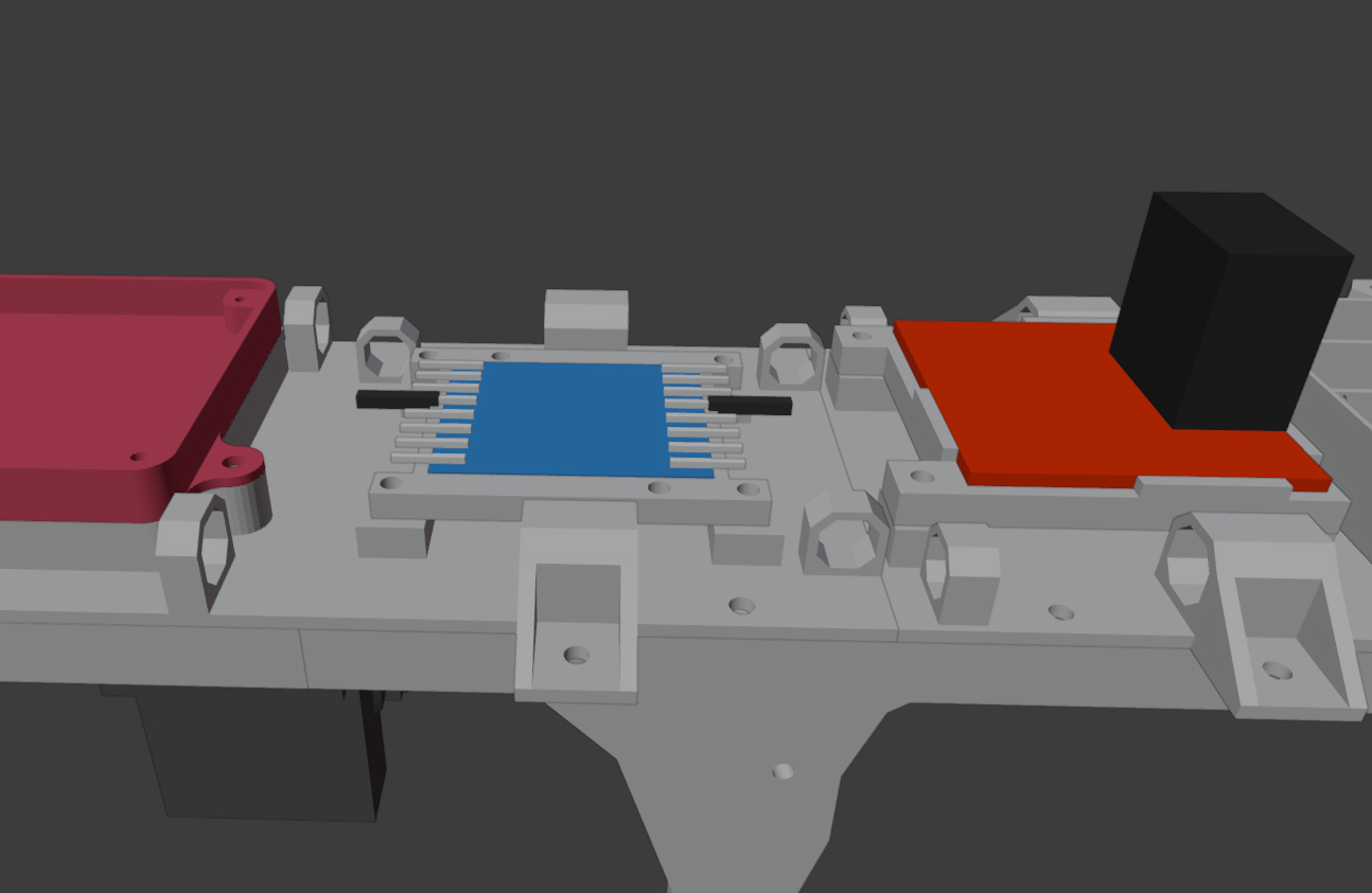
Installation and connection of equipment
Equipment composition:
- Raspberry Pi 3 model A+
- Logic level converter from 3.3V to 5V
- L298N brushless motor driver
- Battery 5V 2700 mAh
- MG995 servo
- Brushless motor
All of the listed equipment can be ordered in any online radio components store. Except for the Raspberry Pi, which sometimes has to be searched for separately.
So let’s begin; first, it is necessary to place all electronic boards on a special platform located on the frame of our truck. They are fixed using small M1 screws.
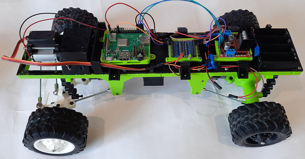
Then, following the diagram shown below, you need to correctly connect all outputs on our devices. All electronic components were connected using 10-pin (F) – 10-pin (M) jumper wires. First, you will need to twist (or solder) two blanks for branching power from the batteries.
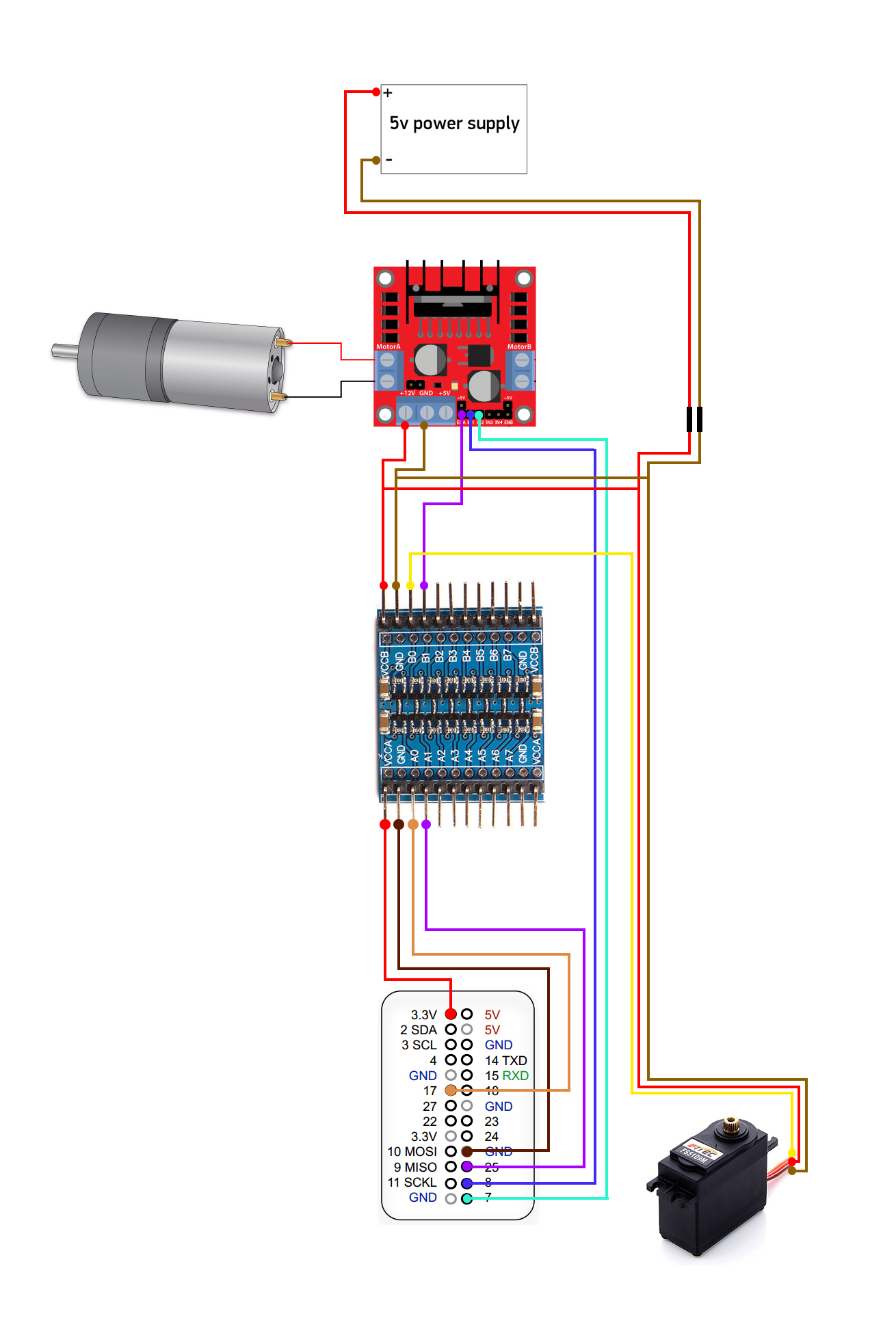
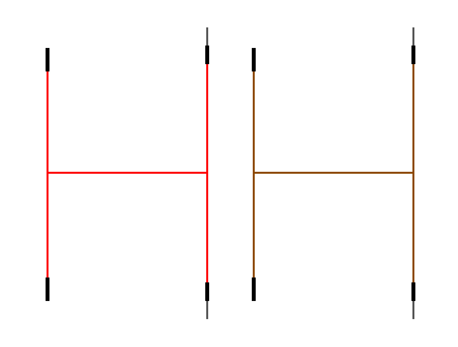
The 5V battery for powering the motors is connected and disconnected using pin connectors. The Raspberry Pi microcomputer is powered separately from an external power bank for mobile devices with a capacity of 9000 mAh, an output voltage of 5V, and a current of 2A.
For further manipulations, it is necessary to check the correctness of the circuit connection. To do this, simply connect the batteries to the motor controllers and the controllers themselves to the Raspberry Pi, connect remotely to the Raspberry via SSH (or connect a monitor for testing), and run a couple of test scripts to check the operation of the servo and brushed motor from the previous articles. If everything works properly, we can move on and start developing a mobile application to control our truck.
Development of a mobile application with a control panel
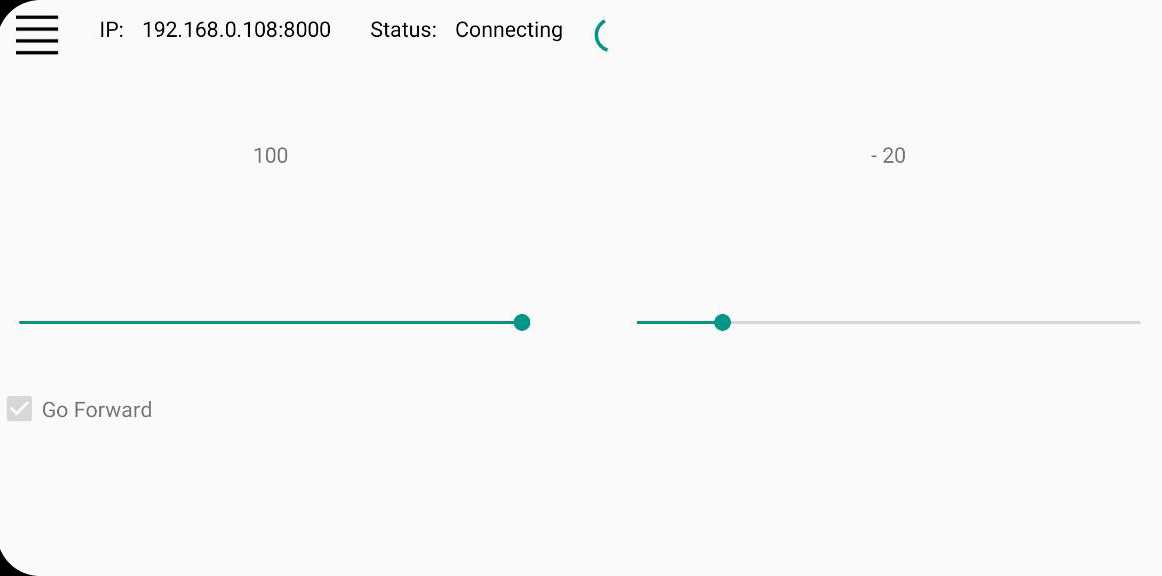
To control the motors of the truck model, a mobile Android application with a minimalist design was developed. A new screen was added to the application for controlling the servo; it is available from the menu item “Servo control”. In the settings, two new fields appeared, “Motor PWM” and “Servo turn”, for specifying the pin numbers for pulse-width modulation (PWM) of the brushed motor, to control smoothness of movement, and for turning the servo, respectively.
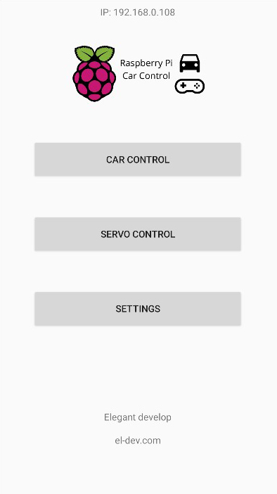
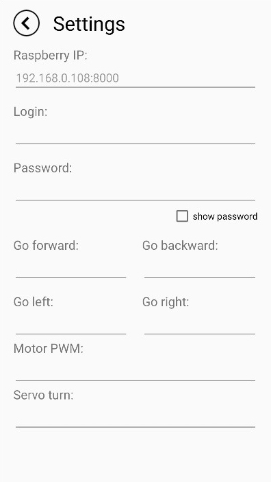
On the settings screen in the application, you must specify the address and port for connecting to the Raspberry Pi, as well as the numbers of the Raspberry Pi pins responsible for controlling the motors. We will not need the “Go left” and “Go right” fields, since turning is performed using the servo.
Here is a description of the correct field values if connecting according to the diagram presented above:
Go forward: 8 (Brushless motor forward movement)
Go back: 7 (Brushless motor backward movement)
Motor PWM: 25 (Pulse-width modulation)
Servo turn: 17 (Servo turning)
After saving the settings, the application will send HTTP requests to the Raspberry Pi to activate the corresponding pins.
Mini web server code in Python
In order for the Raspberry Pi to understand our commands and activate the necessary pins, a small web application written in Python was developed. Before connecting through the mobile application, you must run the Python script with the code specified below. This web server has an open API interface with commands; by calling them, you can control the motors connected to the Raspberry Pi.
 from flask import Flask, json, request
from werkzeug.serving import make_server
import RPi.GPIO as GPIO
import threading
import time

app = Flask(__name__)

p_servo = 17  # GPIO num for servo
fPWM = 50  # Hz (not higher with software PWM)
a = 10
b = 2

in1 = 23  # GPIO num for motor go forward
in2 = 24  # GPIO num for motor go backward
p_motor = 18  # GPIO num for PWM control motor
go_forward = 1

min_angle = 30
max_angle = 90
default_forward_angle = 60

throttle_current = 0

is_making_connection = 0

class ServerThread(threading.Thread):

    def __init__(self, app):
        threading.Thread.__init__(self)
        self.srv = make_server('0.0.0.0', 5000, app)
        self.ctx = app.app_context()
        self.ctx.push()

    def run(self):
        print('starting server')
        try:
            self.srv.serve_forever()
        finally:
            self.srv.server_close()

    def shutdown(self):
        print('server stopped now !')
        self.srv.shutdown()
        self.srv.server_close()


@app.route('/')
def hello_world():
    return 'Hello, from Raspberry Pi!'

@app.route('/set-servo-angle')
def set_servo_angle():
    servo_angle = request.args.get('servo_angle')
    if servo_angle != 'None':
        setDirection(servo_angle)
        #return '{"status":"ok"}'
    #else:
        #return '{"status":"err", "err_msg":"empty servo_angle parameter"}'
    return 'ok'


@app.route('/set-throttle')
def set_throttle():
    throttle_val = request.args.get('throttle_val')
    if throttle_val != 'None':
        setThrottle(int(throttle_val))
        # return '{"status":"ok"}'
    # else:
    # return '{"status":"err", "err_msg":"empty throttle_val parameter"}'
    return 'ok'


@app.route('/set-go-forward')
def set_go_forward():
    global go_forward
    go_forward_val = request.args.get('go_forward')
    if throttle_current == 0 and go_forward_val != 'None':
        go_forward = int(go_forward_val)
        return '{"status":"ok"}'
    else:
        return '{"status":"err", "err_msg":"empty go_forward parameter"}'


@app.route('/make-connection')
def make_connection():
    pwm_servo = request.args.get('p_servo')
    pwm_motor = request.args.get('p_motor')
    inpt1 = request.args.get('in1')
    inpt2 = request.args.get('in2')
    if pwm_servo != 'None' and pwm_motor != 'None' and inpt1 != 'None' and inpt2 != 'None':
        setup(int(pwm_servo), int(pwm_motor), int(inpt1), int(inpt2))
        return '{"status":"ok"}'
    else:
        return '{"status":"err", "err_msg":"empty setup GPIO parameters"}'


@app.route('/exit')
def app_exit():
    setDirection(default_forward_angle)
    time.sleep(5)
    GPIO.cleanup()
    print("stopping server")
    stop_server()
    return "Server closed"


def setup(pwm_servo_val, pwm_motor_val, inpt1, inpt2):
    global servo_pwm, motor_pwm, in1, in2, p_servo, p_motor, is_making_connection
    # global servo_pwm, motor_pwm, is_making_connection

    if is_making_connection == 0:
        p_servo = pwm_servo_val
        p_motor = pwm_motor_val
        in1 = inpt1
        in2 = inpt2

        print('Setup: p_servo {} | p_motor {} | in1 {} | in2 {}'.format(p_servo, p_motor, in1, in2))

        GPIO.setmode(GPIO.BCM)
        GPIO.setup(p_servo, GPIO.OUT)
        GPIO.setup(in1, GPIO.OUT)
        GPIO.setup(in2, GPIO.OUT)
        GPIO.setup(p_motor, GPIO.OUT)
        GPIO.output(in1, GPIO.LOW)
        GPIO.output(in2, GPIO.LOW)
        motor_pwm = GPIO.PWM(p_motor, 1000)
        motor_pwm.start(throttle_current)
        servo_pwm = GPIO.PWM(p_servo, fPWM)
        servo_pwm.start(getDutyFromAngle(default_forward_angle))
        is_making_connection = 1


def getDutyFromAngle(angle):
    duty = float(angle) / (180 / (10)) + 2.0
    duty = round(duty, 2)
    print("getDutyFromAngle: duty = ", duty)
    return duty


def setDirection(angle):
    # duty = a / 120 * direction + b
    angle = ((int)(angle))
    print('setDirection: ', angle)

    if angle >= max_angle:
        angle = max_angle
    elif angle <= min_angle:
        angle = min_angle

    if min_angle <= angle <= max_angle:
        duty = getDutyFromAngle(angle)
        servo_pwm.ChangeDutyCycle(duty)
        print("direction =", angle, "-> duty =", duty)
        # time.sleep(2) # allow to settle
    return angle


def setThrottle(throttle_val):
    global throttle_current
    print('setThrottle: throttle_current {} | throttle_val {}'.format(throttle_current, throttle_val))
    if throttle_current == 0 and throttle_val > 0:
        startMotor()

    if 0 <= throttle_val <= 100:
        throttle_current = throttle_val
        if throttle_current == 100:
            GPIO.output(p_motor, GPIO.HIGH)
            print('set MAX throttle')
        else:
            motor_pwm.ChangeDutyCycle(throttle_current)  # change motor PWM to move
            print("setThrottle(): throttle_current = ", throttle_current)
        if throttle_current == 0:
            stopMotor()


def startMotor():
    if go_forward == 1:
        GPIO.output(in1, GPIO.HIGH)
        GPIO.output(in2, GPIO.LOW)
        print('start motor go forward')
    elif go_forward == 0:
        GPIO.output(in1, GPIO.LOW)
        GPIO.output(in2, GPIO.HIGH)
        print('start motor go backward')


def stopMotor():
    GPIO.output(in1, GPIO.LOW)
    GPIO.output(in2, GPIO.LOW)
    print('stop motor')


def start_server():
    global server
    server = ServerThread(app)
    server.start()
    print('server started')


def stop_server():
    global server
    server.shutdown()


def main():
    # setup()
    start_server()


if __name__ == '__main__':
    main()
Launch and testing
Before starting the model, you must connect power from the external battery to the Raspberry Pi. After the Raspberry Pi boots and you successfully connects to it via SSH, you can connect the additional battery to the circuit of our motors. The LEDs on the body of the brushed motor driver should light up.
It is worth recalling that the WebIOPi service must be installed and running on the Raspberry Pi (for more details, see the previous article).
If everything is specified correctly in the application settings, open the “Servo Control” screen, the connection status should change to “Connected”, after which you can begin controlling the model’s motors. The detailed process of launching and testing the model can be seen in the video below.
Conclusions
Insufficient battery power for powering the motors. The current power of 4.8V is insufficient to power the servo and the brushless motor. As a result, the rotational force of the brushless motor is barely enough to move the model from its place. In the next article, we will try to connect 4 more GP batteries of 1.2V in series to achieve a full 9V and install a more powerful motor. It is necessary to lubricate the rubbing parts. This concerns the plastic gears inside the front and rear axles, the differential, and the gearbox. It is necessary to print an external body to protect the electronics from dust. The shape of the body will repeat the form factor of a real truck. We will implement this in the next article.
2. 3D model from Blender and STL files of the electronics platform
3. Project with application source code on GitHub: CarControl
4. Link to the project on the Thingiverse: 3D printed RC truck
